
Page 137 - IJB-8-2
P. 137
Li, et al.
thus blocking the cavity of the microneedle. All the HMNs of the substrate should be consistent with the arrangement
can be fabricated by a single exposure within 5 s. These of the large white circles. A 10 × 6 mm HMNP could be
results indicate that SOPL technology can flexibly and formed within 5 s via rapid photopolymerization. SEM
rapidly customize HMNs with various structures, which showed that the height of each HMN was about 1000
may have broader applications. For instance, HMNs with μm. HMNs had distinct opening and sharp tip without
large openings can be made into coated HMNs, which the layered structure commonly associated with other 3D
would increase drug loading efficiency . printing methods (Figure 4B).
[29]
HMNPs can be fabricated by sequentially exposing In short, to fabricate the ideal HMNPs, the first step
printing pictures of HMN arrays and substrates. SOPL is to design printing pictures. For example, the sizes of
technique can customize HMN arrays with various the large white circle and the small black circle, which
alignments by designing printing pictures. For example, are related to the sizes of the bottom and opening of the
HMNPs with the aligned arrangement and dislocated HMNs. The relative position of the small black circle
arrangement were portrayed in Figure 4A and B, and the white circle is designed to prepare the suitable
respectively. As shown in Figure 4A, a 5 × 8 aligned structure of HMN. The arrangement between the large
HMNP could be obtained by exposing the specific printing white circles and the shape of the substrate determines
pictures of the HMN array and the substrate in sequence. the distribution of the microneedle array and the structure
The dislocation-arranged HMNP could be prepared of the patch respectively. Then, according to the designed
by changing the arrangement of the printing pictures printing pictures, digital light allows the photosensitive
(Figure 4B). It was worth noting that the printing picture materials to rapidly polymerize to form the HMNP
A B C D E
Figure 3. The morphologies of HMNs with different opening positions observed by SEM (Scale bars: 500 μm). (A-C) HMNs had holes at
the bottom. (D-E) HMNs had no holes at the bottom.
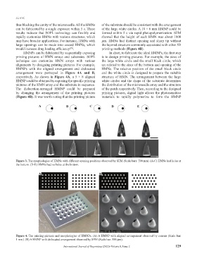
A B
Figure 4. The printing pictures and morphologies of HMNPs. (A) A HMNP with aligned arrangement observed by camera (Scale bar:
1 mm). (B) A HMNP with dislocated arrangement observed by SEM (Scale bar: 500 μm).
International Journal of Bioprinting (2022)–Volume 8, Issue 2 129