
Page 66 - IJB-8-3
P. 66
Extrusion of two-vasculature scaffold for angiogenesis
A B
C D
E F
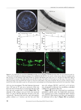
Figure 5. The fabricated two-vasculature-embedded scaffold; (A) the generated scaffold in the Petri dish after the formation (scale bar:
10 mm); (B) The bright-field microscope images of the scaffold with the HUVEC core and the hollow channel after the formation (scale
bar: 200 µm); (C) The diameter of the shell and the two channels with the flow rate of the cores as 0.1 mL/min and various flow rates of
the shell; (D) the diameter of the shell and the cores with the flow rate of the shell as 2 ml/min and various flow rates of the cores; (E) the
fluorescent image of the stained HUVECs inside the fabricated scaffold after 1-day culture (scale bar: 100 µm). (F) The confocal image of
the HUVECs after 2-day culture (scale bar: 200 µm) and the cross-sectional view of the lumen structure in the HUVECs (scale bar: 30 µm).
shift was also investigated. The shell diameter decreased rate with collagen, HUVEC, and CaCl as 0.1 mL/min
2
from 1067 µm to 951 µm in an increment of the core were designated to fabricate two-vasculature-embedded
flow rate from 0.05 mL/min to 0.2 mL/min when the shell scaffolds for experiment with cells.
flow rate was constant with 2 mL/min (Figure 5D). The Figure 5B shows the formulated two-vasculature-
diameter of the collagen core and CaCl core increased embedded scaffold under the bright-field microscope.
2
from 191 µm to 409 µm and from 165 µm to 281 µm, Two separated cores with a transparent hollow channel
respectively. Therefore, the shell flow rate with alginate- and a HUVEC filled channel were observed. Aggregation
gelatin mixture as 2 mL/min and the two-core flow of individual cells at day 0 (Figure 5B) has gradually
58 International Journal of Bioprinting (2022)–Volume 8, Issue 3