
Page 67 - IJB-8-3
P. 67
Nguyen, et al.
stretched, migrated, and connected to produce ECs’ significantly up to about 100 µm apart from the edge of
networks after 1 day of culture (Figure 5E). Confocal the channel.
images of the HUVEC core exhibited a hollow center Perfusibility of the HUVEC vessel was evaluated
in cross-section view (Figure 5F). HUVEC has the with blue fluorescence microbead, as shown in Figure 8
propensity to form luminal structures in the three- and Supplementary Video. The blue fluorescence
dimensional matrix , which can be perfused [18,22,23] . microbead flowed continuously in the HUVEC vessel.
[22]
It showed that the embedded HUVECs have well
3.2. Perfusability developed into the vascular structure. Even though the
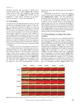
To optimize flow rate through the hollow channel, the red syringe pump drove the blue microbead identically to
dye has flowed through the hollow channel of the cell- both channels at the flow rate of 10 µL/min, the hollow
free two-vasculature-embedded scaffold, as shown in channel flowed much more microbeads than the HUVEC
Figure 6. The flow rates over 10 µL/min have diffused vessel (Figure 8B). It was presumed that the HUVEC
into all parts of the scaffold in 10 min. However, 2 µL/ vessel had much more bumpy structures than the hollow
min and 5 µL/min required 15 min for the entire diffusion. channel for the microbead to pass through.
Even though it diffused at all parts of the scaffold, its 3.3. Cell morphology according to the culture
color gradient differed according to the flow rate. As the
flow rate increased, its red color became deep in less time. condition
However, in our previous study [24,25] , the flow rate over 20 Different F-actin expression of the embedded HUVECs
µL/min has made the linking part from the connecting was observed according to the culture condition, as
device to the scaffold loosen in a short time. Therefore, shown in Figure 9. The cells in the obstructing condition
10 µL/min was selected for the secure connection in this exhibited arbitrary size and cobblestone-like morphology
investigation. with random orientation (Figure 9A). The soaking
Fluorescence fluid was also pumped into the hollow condition showed spindle-like morphology doped in the
channel with the flow rate of 10 µL/min until 60 min to cobblestone-like morphology with random orientation
understand diffusion in our scaffold. Figure 7 presented (Figure 9B). Particularly, the cells in the flowing
the temporal sequence of the fluorescence microscope condition presented uniform spindle-like morphology
images. Based on the temporal images, fluorescence with the arrangement in the flow direction (Figure 9C).
intensity was analyzed. The most gray value at 1 time point These results indicated that cell elongation and alignment
showed an increasing tendency as time went (Figure 7B). of the flowing condition are similar in vivo . For further
[26]
The integrated density exhibited a similar tendency with quantitative analysis, three morphometric parameters of
the most gray value (Figure 7C). Considering these the embedded HUVECs, namely, perimeter, elongation
two graphs, 15 min was a meaningful time to diffuse ratio, and orientation deviation (Figure 9D-F), were
Figure 6. The time-lapse images of the perfused channel from 5 min to 30 min at various flow rates (scale bar: 1 mm).
International Journal of Bioprinting (2022)–Volume 8, Issue 3 59