
Page 71 - IJB-8-3
P. 71
Nguyen, et al.
A
B
C
D
E
F
G H
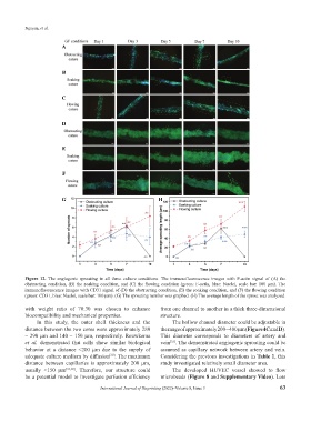
Figure 12. The angiogenic sprouting in all three culture conditions. The immunofluorescence images with F-actin signal of (A) the
obstructing condition, (B) the soaking condition, and (C) the flowing condition (green: F-actin, blue: Nuclei, scale bar: 100 µm). The
immunofluorescence images with CD31 signal of (D) the obstructing condition, (E) the soaking condition, and (F) the flowing condition
(green: CD31, blue: Nuclei, scale bar: 100 µm). (G) The sprouting number was graphed. (H) The average length of the sprout was analyzed.
with weight ratio of 70:30 was chosen to enhance from one channel to another in a thick three-dimensional
biocompatibility and mechanical properties. structure.
In this study, the outer shell thickness and the The hollow channel diameter could be adjustable in
distance between the two cores were approximately 280 the range of approximately 200 – 400 µm (Figure 4C and D).
– 290 µm and 140 – 150 µm, respectively. Rouwkema This diameter corresponds to diameters of artery and
et al. demonstrated that cells show similar biological vein . The demonstrated angiogenic sprouting could be
[33]
behavior at a distance <200 µm due to the supply of assumed as capillary network between artery and vein.
adequate culture medium by diffusion . The maximum Considering the previous investigations in Table 1, this
[30]
distance between capillaries is approximately 200 µm, study investigated relatively small diameter area.
usually <150 µm [31,32] . Therefore, our structure could The developed HUVEC vessel showed to flow
be a potential model to investigate perfusion efficiency microbeads (Figure 8 and Supplementary Video). Lots
International Journal of Bioprinting (2022)–Volume 8, Issue 3 63