
Page 69 - IJB-8-3
P. 69
Nguyen, et al.
A B C
D E F
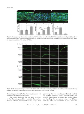
Figure 9. The morphology characterization in the HUVEC channel on day 2; the stained HUVECs in (A) the obstructing condition, (B) the
soaking condition, and (C) the flowing condition (scale bar: 50 µm). The quantification of (D) the perimeter, (E) the elongation ratio, and (f)
the orientation deviation of the stained HUVECs.
A
B
Figure 10. The fluorescence images of the live-/dead-stained HUVECs at the obstructing condition, the soaking condition, and the flowing
condition (A) without the additional GFs and (B) with the additional GFs (scale bar: 200 µm).
the soaking condition (79.3%). However, they were not generating the two-vasculature-embedded scaffold,
statistically different from each other. the soaking condition caused only the formulated
The results indicated that the glass capillary scaffold immediately submerge into media without
of the obstructing condition restricted the medium any handling for connection, which was different
diffusion into the embedded HUVECs. Right after from the other two conditions. It could make the
International Journal of Bioprinting (2022)–Volume 8, Issue 3 61