
Page 276 - IJB-8-4
P. 276
Multifunctional 3D Bioprinting System for Construction of Complex Tissue Structure Scaffolds
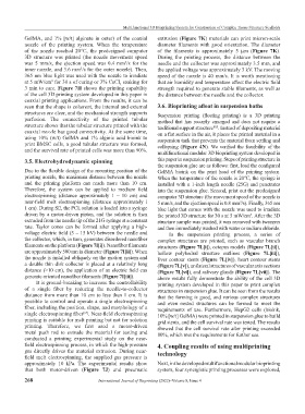
GelMA, and 1% [w/t] alginate in outer) of the coaxial extrusion (Figure 7K) materials can print micron-scale
nozzle of the printing system. When the temperature diameter filaments with good orientation. The diameter
of the nozzle reached 20°C, the predesigned computer of the filaments is approximately 5 μm (Figure 7K).
3D structure was printed (the nozzle movement speed During the printing process, the distance between the
was 5 mm/s, the ejection speed was 0.4 mm /s for the needle and the collector was approximately 3.5 mm, and
3
inner nozzle, and 3.6 mm /s for the outer nozzle). Then, the applied voltage was approximately 3 kV. The moving
3
365 nm blue light was used with the nozzle to irradiate speed of the nozzle is 40 mm/s. It is worth mentioning
at 5 mW/cm for 30 s of curing or 3% CaCl soaking for that air humidity and temperature affect the electric field
2
2
3 min to cure. Figure 7H shows the printing capability strength required to generate stable filaments, as well as
of the cell 3D printing system developed in this paper in the distance between the needle and the collector.
coaxial printing applications. From the results, it can be
seen that the shape is coherent, the internal and external 3.6. Bioprinting afloat in suspension baths
structures are clear, and the mechanical strength supports Suspension printing (floating printing) is a 3D printing
perfusion. The connectivity of the printed tubular method that has recently emerged and does not require a
structure shows that the tubular structure printed with the traditional support structure . Instead of depositing material
[65]
coaxial nozzle has good connectivity. At the same time, on a flat surface in the air, it places the printed material in a
using 10% (w/t) GelMA and 1% alginic acid bioink to suspension tank that prevents the material from settling and
print BMSC cells, a good tubular structure was formed, collapsing (Figure 4N). We verified the feasibility of the
and the survival rate of printed cells was more than 90%.
multifunctional modular 3D bioprinting system developed in
3.5. Electrohydrodynamic spinning this paper in suspension printing. Steps of printing structure in
the suspension glue are as follows: first, load the configured
Due to the flexible design of the mounting position of the GelMA bioink on the print head of the printing system.
printing nozzle, the maximum distance between the nozzle When the temperature of the nozzle is 20°C, the syringe is
and the printing platform can reach more than 10 cm. installed with a 1-inch length needle (25G) and penetrates
Therefore, the system can be applied to medium field into the suspension glue. Second, print out the predesigned
electrospinning (distance approximately 1 ~ 10 cm) and computer 3D structure (the movement speed of the nozzle is
near-field melt electrospinning (distance approximately i 5 mm/s, and the ejection speed is 0.8 mm /s). Finally, 365 nm
3
1 cm). During SE, the PCL solution is loaded into a syringe blue light that comes with the nozzle was used to irradiate
driven by a motor-driven piston, and the solution is then the printed 3D structure for 30 s at 5 mW/cm . After the 3D
2
extruded from the needle tip of the 21G syringe at a constant structure sample was printed, it was removed with tweezers
rate. Taylor cones can be formed after applying a high- and then immediately washed with water or sodium chloride.
voltage electric field (5 – 15 kV) between the needle and In the suspension printing process, a series of
the collector, which, in turn, generates disordered nanofiber complex structures are printed, such as vascular branch
filaments on the platform (Figure 7I[i]). Nanofiber filaments structures (Figure 7L[i]), octopus models (Figure 7L[ii]),
are approximately 500 nm in diameter (Figure 7I[ii]). When hollow polyhedral structure outlines (Figure 7L[iii]),
the nozzle is installed obliquely on the motion system and liver contour stents (Figure 7L[iv]), heart contour stents
a double thin disk collector is placed at a relatively long (Figure 7L[v]), unilateral structures of vascular axis sections
distance (>10 cm), the application of an electric field can (Figure 7L[vi]), and salivary glands (Figure 7L[vii]). The
generate oriented nanofiber filaments (Figure 7I[iii]). above results fully demonstrate the ability of the cell 3D
It is ground-breaking to increase the controllability printing system developed in this paper to print complex
of a single fiber by reducing the needle-to-collector structures in suspension glue. It can be seen from the results
distance from more than 10 cm to less than 1 cm. It is that the forming is good, and various complex structures
possible to control and operate a single electrospinning and even nested structures can be formed to meet the
fiber, including the position, shape, and morphology of a requirements of use. Furthermore, HepG2 cells (bioink,
single electrospinning fiber . Near-field electrospinning 10% [w/t] GelMA) were printed in suspension glue to build
[64]
printing is suitable for melt printing but not for solution grid stents, and the cell survival rate was tested. The results
printing. Therefore, we first used a motor-driven showed that the cell survival rate after printing exceeded
metal push rod to extrude the material for testing and 80%, which met the requirements for further use.
conducted a printing experimental study on the near-
field electrospinning process, in which the high-pressure 4. Coupling results of using multiprinting
gas directly drives the material extrusion. During near- technology
field melt electrospinning, the supplied gas pressure is
approximately 10 kPa. The experimental results show Next, in the developed multifunctional modular bioprinting
that both motor-driven (Figure 7J) and pneumatic system, four synergistic printing processes were explored,
268 International Journal of Bioprinting (2022)–Volume 8, Issue 4