
Page 251 - IJB-9-3
P. 251
International Journal of Bioprinting Multi-material bioprinting with OCT imaging
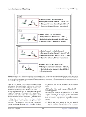
Figure 3. Time-related nozzle control model. (A) Nozzle control model 1. A1 is the first case where the starting point of nozzle 2 is connected to the starting
point of nozzle 1; A2 is the second case where the ending point of nozzle 2 is connected to the ending point of nozzle 1. (B) Nozzle control model 2. B1 is
the first case where the ending point of nozzle 2 is connected to the starting point of nozzle 1; B2 is the second case where the ending point of nozzle 2 is
connected to the starting point of nozzle 1.
When starting point of nozzle 2 was connected with the print strategies were used in the connection point between
ending point of nozzle (starting-point-ending-point), this nozzles.
situation was the same as that of end-point-starting-point,
the AET of nozzle 2 (T ) and the ATEP of nozzle 1 (X ) 2.5. Workflow of the multi-nozzle, multi-material
2
1
are corrected through once or twice that achieve good bioprinting process
extrusion. For example, if separated path between the two The flowchart of the printing process with the proposed
materials occurs at this point, T is to be updated; if this method is illustrated in Figure 5. The printing requirements
2
point has excessive material deposition, X is to be updated. are determined in advance, and the following steps can be
1 taken to achieve a high-precision registration between
Using the print path shown in Figure 4A, the materials.
connections point between nozzles were shown in area 1
and area 2. Combination of the print path and different (i) Step 1: The static models for the used materials
printing methods as shown in Figure 4B and C, the above are retrieved and the optimal printing parameters
Volume 9 Issue 3 (2023) 243 https://doi.org/10.18063/ijb.707