
Page 256 - IJB-9-3
P. 256
International Journal of Bioprinting Multi-material bioprinting with OCT imaging
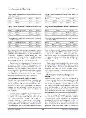
Table 1. Initial control parameters of nozzle 1 and nozzle 2 in Table 4. Control parameters 2 of nozzle 1 and nozzle 2 in
nozzle control model 1 initial state
Position Controlled parameters Nozzle 1 Nozzle 2 Position Nozzle 1 Nozzle 2
Area 1 AET (T) 60 ms 0 ms Area 1 AET (T) 0 ms ATEP (X) 0 mm
Area 2 ATEP (X) 0 mm 0 mm Area 2 ATEP (X) 0 mm AET (T) 0 ms
Table 2. Control parameters 1 of nozzle 1 and nozzle 2 in Table 5. Initial control parameters of nozzle 1 and nozzle 2 in
initial state nozzle control model 2
Position Controlled parameters Nozzle 1 Nozzle 2 Position Nozzle 1 Nozzle 2
Area 1 AET (T) 60 ms 60 ms Area 1 AET (T) 0 ms ATEP (X) 1 mm
Area 2 ATEP (X) 0.5 mm 0.8 mm Area 2 ATEP (X) 1 mm AET (T) 0 ms
Table 3. Optimized control parameters for nozzle 1 and nozzle Table 6. Optimized control parameters for nozzle 1 and nozzle
2 control in model 1 2 control in model 2
Position Controlled parameters Nozzle 1 Nozzle 2 Position Nozzle 1 Nozzle 2
Area 1 AET (T) 60 ms 60 ms Area 1 AET (T) 0 ms ATEP (X) 0.8 mm
Area 2 ATEP (X) 0.5 mm 0.6 mm Area 2 ATEP (X) 0.7 mm AET (T) 0 ms
shown in Figure 8A3, the printing result started to connect 15 px, the distance of early terminate extrusion should be
at the point of area 1, and there was no need to continue to 0.2371 mm. Thus, the ATEP of nozzle 2 was updated to
update the control parameters of the two nozzles in area 0.8 mm (X = 1 - 0.2371 ≈ 0.8 mm). Area 2 also had a
2
1. There was a separation of printed paths in area 2. The separation of printed paths, and the average pixel size of
average pixel size of the interval was 10 px, and the separated the middle interval was about 12.5 px, that is, 0.2914 mm.
distance was 0.194 mm. Therefore, the ATEP of nozzle 2 The ATEP of nozzle 1 was updated to 0.7 mm (X = 1 -
1
was changed to 0.6 mm (X = 0.8 - 0.194 ≈ 0.6 mm). 0.2914 ≈ 0.7 mm).
2
The optimized control parameters of the two nozzles The optimized control parameters for the two nozzles
are shown in Table 3. The OCT data projection and are listed in Table 6. Figure 8B4 shows the reconstructed
reconstruction of area 1 and area 2 are shown in Figure 8A4, OCT models of area 1 and area 2. After the nozzle control
respectively. The two materials at area 1 and area 2 had parameters were optimized, the two materials showed a
been connected, and there was no over-extrusion or under- good connection without overlapping material in area 1
extrusion. Therefore, the nozzle parameters listed in Table 3 and area 2.
were optimization parameters for the condition where the
two nozzles share the same starting or ending point. 3.3. Multi-material bioprinting of single-layer
scaffold
3.2.2. Experiment of nozzle control for model 2 According to the results of the corner optimization of
The path and printing method of the ending/starting- the above path and the results of optimizing the nozzle
point-starting/ending-point are shown in Figure 8B1. The parameters, the different printing methods of the single-
printing parameters of both nozzles were not set in area 1 layer support were designed, as shown in Figures 9A and
or area 2, as shown in Table 4. At this time, there was over- 10A. The spacing between the two materials at the middle
extrusion in area 1 and area 2, as shown in Figure 8B2. corner was designed to be 0.45 mm, the printing corner
Therefore, the model of nozzle control was adopted for speed was increased to 7 mm/s at 0.5 mm in advance of the
area 1 and area 2. corner and 0.5 mm out of the corner, and the printing speed
of the remaining straight lines was maintained at 6 mm/s.
First, the printing parameters set for the two nozzles
are listed in Table 5. No AET was set for nozzle 1 at area 1 When the starting and ending points of the two nozzles
(T is 0 ms), and ATEP of nozzle 2 (X ) was set to 1 mm. At were coincided, according to the optimization results of
2
1
area 2, the ATEP of nozzle 1 (X ) was 1 mm, and the AET the above nozzle control parameters, the optimization
1
of nozzle 2 remained 0 (T is 0 ms). The OCT projection parameters of the control nozzle are shown in Table 3. In
2
images of area 1 and area 2 are shown in Figure 8B3. The area 1, the AET of nozzle 1 and nozzle 2 were both set to
printing path between the materials in area 1 was separated. 60 ms. In area 2, the ATEP of nozzle 1 was set to 0.5 mm,
The average pixel size of the middle interval was about and that of nozzle 2 was set to 0.6 mm in advance. We
Volume 9 Issue 3 (2023) 248 https://doi.org/10.18063/ijb.707