
Page 184 - IJB-9-6
P. 184
International Journal of Bioprinting 3D-printed assembly anatomical patella fracture bone plate
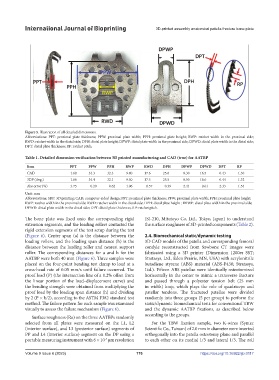
Figure 5. Illustration of all detailed dimensions.
Abbreviations: PPT: proximal plate thickness; PPW: proximal plate width; PPH: proximal plate height; RWP: ratchet width in the proximal side;
RWD: ratchet width in the distal side; DPH: distal plate height; DPWP: distal plate width in the proximal side; DPWD: distal plate width in the distal side;
DPT: distal plate thickness; RP: ratchet pitch.
Table 1. Detailed dimension verification between 3D printed manufacturing and CAD (true) for AATBP
Item PPT PPW PPH RWP RWD DPH DPWP DPWD DPT RP
CAD 1.60 34.3 32.3 9.40 17.6 25.6 8.30 16.5 0.43 1.30
3DP (Avg.) 1.66 34.4 32.1 9.50 17.5 25.5 8.50 16.6 0.44 1.32
Abs error (%) 3.75 0.29 0.62 1.06 0.57 0.39 2.41 0.61 2.33 1.54
Unit: mm
Abbreviations: 3DP: 3D printing; CAD: computer-aided design; PPT: proximal plate thickness; PPW: proximal plate width; PPH: proximal plate height;
RWP: ratchet width in the proximal side; RWD: ratchet width in the distal side; DPH: distal plate height ; DPWP: distal plate width in the proximal side;
DPWD: distal plate width in the distal side; DPT: distal plate thickness; RP: ratchet pitch.
The bone plate was fixed onto the corresponding rigid (SJ-210, Mitutoyo Co, Ltd., Tokyo, Japan) to understand
extension segments, and the loading rollers contacted the the surface roughness of 3D-printed components (Table 2).
rigid extension segments of the test setup during the test
(Figure 6). Center span (a) is the distance between the 2.4. Biomechanical static/dynamic testing
loading rollers, and the loading span distance (h) is the 3D CAD models of the patella and corresponding femoral
distance between the loading roller and nearest support condyle reconstructed from Sawbone CT images were
roller. The corresponding distances for a and h for the fabricated using a 3D printer (Dimension 1200es SST;
AATBP were both 40 mm (Figure 6). Three samples were Stratasys, Ltd., Eden Prairie, MN, USA) with acrylonitrile
placed on the four-point bending test clamp to load at a butadiene styrene (ABS) material (ABS-P430; Stratasys,
cross-head rate of 0.05 mm/s until failure occurred. The Ltd.). Fifteen ABS patellae were identically osteotomized
proof load (P) (the intersection line of a 0.2% offset from horizontally in the center to mimic a transverse fracture
the linear portion of the load–displacement curve) and and passed through a polyester tension belt (25 mm
the bending strength were obtained from multiplying the in width) loop, which plays the role of quadriceps and
proof load by the loading span distance (h) and dividing patellar tendons. The fractured patellae were divided
by 2 (P × h/2), according to the ASTM F382 standard test randomly into three groups (5 per group) to perform the
method. The failure pattern for each sample was examined static/dynamic biomechanical tests for conventional TBW
visually to assess the failure mechanism (Figure 6). and the dynamic AATBP fixations, as described below
according to the groups.
Surface roughness (Ra) on the three AATBPs randomly
selected from all plates were measured on the L1, L2 For the TBW fixation sample, two K-wires (Syntec
(interior surface), and L3 (posterior surface) segments of Scientific Co., Taiwan) of 2.0 mm in diameter were inserted
PP and L4 (interior surface) segment on the DP using a orthogonally into the patella osteotomy plane and parallel
portable measuring instrument with 6 × 10 µm resolution to each other on its medial 1/3 and lateral 1/3. The roll
-3
Volume 9 Issue 6 (2023) 176 https://doi.org/10.36922/ijb.0117