
Page 185 - IJB-9-6
P. 185
International Journal of Bioprinting 3D-printed assembly anatomical patella fracture bone plate
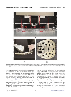
Figure 6. (a) Illustration of the four-point bending test according to ASTM F382; the AATBP was fixed onto the corresponding rigid extension segments;
the loading rollers contacted the rigid extension segments of the test setup during the test; (b) locking screw loosening after test; and (c) the position of
the AATBP damage.
wire loop (Syntec Scientific Co., Taiwan) with a diameter much as possible to coincide with the anterior curved
of 1.25 mm was laid around the protruding K-wire ends, surface of the patella before being secured. Five locking
forming a figure-of-eight on the patella anterior surface. and three compressive screws of 2.4 mm in diameter (A
Two knots were twisted into the distal part of the K-wire Plus Biotechnology Co. Ltd, Taipei, Taiwan) distributed
and tightened. The proximal part of the K-wire was bent, with medial–lateral symmetry were inserted into PP and
cut, and impacted to ensure its complete contact with the DP, respectively, to fix the fractured patella. These screws
[15]
ABS bone surface (Figure 7a) . spanned the fracture gap (Figure 7a).
For AATBP fixation, PP and DP were adjusted to To evaluate the PP and distal DP assembly flatness
the assembly using a ratchet mechanism for fitting the through the ratchet teeth, three AATBPs were randomly
patella height (about 46.8 mm) and holding the fractured selected and erected to allow the anterior surface to be
fragments by the corresponding hook pairs passing through positioned parallel to the ARCS light source. This allowed
the belt. The AATBP curved surface can be adjusted as assembly tightness error measurement between the two
Volume 9 Issue 6 (2023) 177 https://doi.org/10.36922/ijb.0117