
Page 187 - IJB-9-6
P. 187
International Journal of Bioprinting 3D-printed assembly anatomical patella fracture bone plate
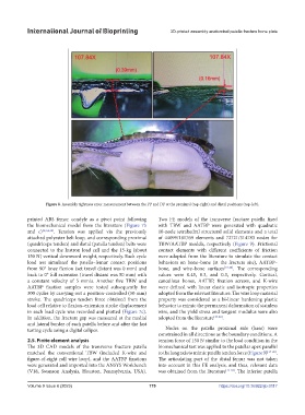
Figure 8. Assembly tightness error measurement between the PP and DP at the proximal (top-right) and distal positions (top-left).
printed ABS femur condyle as a pivot point following Two FE models of the transverse fracture patella fixed
the biomechanical model from the literature (Figure 7b with TBW and AATBP were generated with quadratic
and c) [2,3,4,16] . Tension was applied via the previously 10-node tetrahedral structural solid elements and a total
attached polyester belt loop, and corresponding proximal of 44099/181769 elements and 72721/314783 nodes for
(quadriceps tendon) and distal (patella tendon) belts were TBW/AATBP models, respectively (Figure 9). Frictional
connected to the Instron load cell and the 15-kg (about contact elements with different coefficients of friction
150 N) vertical downward weight, respectively. Each cycle were adopted from the literature to simulate the contact
load test simulated the patella–femur contact positions behaviors on bone–bone (at the fracture site), AATBP–
from 90° knee flexion (set travel distant was 0 mm) and bone, and wire–bone surfaces [17-20] . The corresponding
back to 0° full extension (travel distant was 50 mm) with values were 0.45, 0.3, and 0.3, respectively. Cortical,
a constant velocity of 5 mm/s. Another five TBW and cancellous bones, AATBP, fixation screws, and K-wire
AATBP fixation samples were tested subsequently for were defined with linear elastic and isotropic properties
300 cycles by carrying out a position-controlled (50 mm) adopted from the relevant literature. The wire loop material
stroke. The quadriceps tendon force obtained from the property was considered as a bi-linear hardening plastic
load cell relative to flexion–extension stroke displacement behavior to mimic the permanent deformation of stainless
in each load cycle was recorded and plotted (Figure 7c). wire, and the yield stress and tangent modulus were also
In addition, the fracture gap was measured at the medial adopted from the literature [17-20] .
and lateral border of each patella before and after the last
testing cycle using a digital caliper. Nodes on the patella proximal side (base) were
constrained in all directions as the boundary conditions. A
2.5. Finite element analysis tension force of 150 N similar to the load condition in the
The 3D CAD models of the transverse fracture patella biomechanical test was applied to the patellar apex parallel
matched the conventional TBW (included K-wire and to the long axis to mimic patella tendon force (Figure 9) [17-20] .
figure-of-eight roll wire loop), and the AATBP fixations The articulating part of the distal femur was not taken
were generated and imported into the ANSYS Workbench into account in this FE analysis, and thus, relevant data
(V18, Swanson Analysis, Houston, Pennsylvania, USA). was obtained from the literature [17-20] . The inferior patella
Volume 9 Issue 6 (2023) 179 https://doi.org/10.36922/ijb.0117