
Page 186 - IJB-9-6
P. 186
International Journal of Bioprinting 3D-printed assembly anatomical patella fracture bone plate
Table 2. Surface roughness measured positions for the AATBP and corresponding obtained results
Sample 1 4.135 5.960 5.454 3.323
Sample 2 4.427 5.495 4.438 3.545
Sample 3 4.698 5.325 6.264 3.824
Mean ± Std (µm) 4.42 ± 0.28 5.59 ± 0.33 5.39 ± 0.91 3.56 ± 0.25
Unit: µm
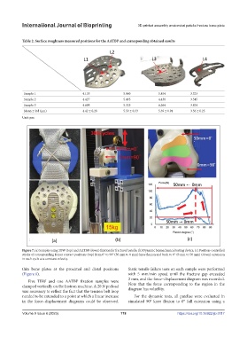
Figure 7. (a) Samples using TBW (top) and AATBP (down) fixation for fractured patella. (b) Dynamic biomechanical testing device. (c) Position-controlled
stroke of corresponding femur contact positions (top) from 0° to 90° (50 mm to 0 mm) knee flexion and back to 0° (0 mm to 50 mm) (down) extension
in each cycle at a constant velocity.
thin bone plates at the proximal and distal positions Static tensile failure tests on each sample were performed
(Figure 8). with 5 mm/min speed until the fracture gap exceeded
Five TBW and one AATBP fixation samples were 2 mm, and the force–displacement diagram was recorded.
clamped vertically on the Instron machine. A 20 N preload Note that the force corresponding to the region in the
was necessary to reflect the fact that the tension belt loop diagram has volatility.
needed to be extended to a point at which a linear increase For the dynamic tests, all patellae were evaluated in
in the force–displacement diagrams could be observed. simulated 90° knee flexion to 0° full extension using a
Volume 9 Issue 6 (2023) 178 https://doi.org/10.36922/ijb.0117