
Page 169 - IJOCTA-15-2
P. 169
J. Gunasekaran et.al / IJOCTA, Vol.15, No.2, pp.354-367 (2025)
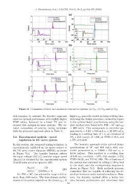
Figure 6. Comparison of servo and regulatory response for systems (a) G p3 , (b) G p4 and (c) G p5
disk margins. In contrast, the iterative approach higher ω gc generally results in faster settling time.
achieves optimal performance with slightly higher Following the design procedure outlined in Figure
ITSE values, balanced by a lower TV and in- 3, the optimal design specifications using the iter-
creased disk margins in most systems. The de- ative method were found to be PM = 90° and ω gc
tailed comparison of existing tuning technique = 400 rad/s. This corresponds to controller pa-
with the proposed approach given in Table 3. rameters b 0 = 3.231 × 10³ and ω c = 20.569 rad/s,
leading to a settling time of 1 s, an overshoot of
5.3. Experimental analysis - speed 2%, a disk margin of 1.339, an ITSE of 16.2, and
regulation in DC servo system a TV of 0.1234.
In this section, the proposed tuning technique is The heuristic approach yields optimal design
experimentally validated on the speed control of specifications of 90° and 800 rad/s with con-
the DC servo motor (Quanser SRV02), as shown troller parameters b 0 = 7.0846 × 10³ and ω c =
in Figure 7(a). The transfer function relates 42.98 rad/sec. This resulted in a settling time
the input voltage (∆V (s)), and the output speed of 0.65 sec, overshoot =16%, disk margin=1.212,
(∆ω l (s)) is obtained by the experimental system ITSE=10.35, and TV=0.1408. The robustness of
identification given in equation (29). the system was evaluated by adding a 300 g load
to the shaft, and the corresponding response is
∆ω l (s) 1.53 shown in Figure 7(d). Both methods generate
= (29)
∆V (s) (0.0254s + 1) controllers that are capable of achieving the de-
For PM = 90°, the admissible range is 0.5 to sired performance under normal conditions. How-
more than 1000 rad/s. The time-domain perfor- ever, the iterative method offers a better bal-
mance of the system depends on the chosen ω gc . A ance between performance and robustness than
364