
Page 166 - IJOCTA-15-2
P. 166
A modified graphical based tuning and performance analysis of second order LADRC . . .
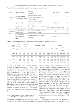
Table 1. Systems considered for performance and comparative study
Equivalent
Section System / Category Transfer function Reference
Applications
DC motor position control
G p1 (Integrating first
Performance (without delay) / Regenerative 36
order plus, delay system)
Study Heat Exchanger
Magnetic levitation system /
2
G p2 (Unstable) Continuous stirred tank reactor 1/(s − 1) 37
(with delay)
G p3 (Second order Two tank interacting system / Boost
2
(
(1.6 e − 0.044s))/(s + 1.32s + 27.8) 38
underdamped system) converter
G p4 (Second order Ball beam system / Twin rotor yaw
Comparative 1/s 2 39
integral system) and pitch control (Quanser)
Study
G p5 (Higher order
Inverted pendulum (with unstable
stable system with (1-2s)/(s+1) 3 20
dynamics)
RHPZ)
Table 2. Optimum time domain performance and robustness for systems G p1 and G p2
Design ADRC tuning
Proposed Time domain Performance Robustness
System specifications parameters
Tuning
Disk
approach PM Disk Gain
(rad/sec) (rad/sec) (rad/sec) (rad/sec) (rad/sec) (rad/sec) (rad/sec) (rad/sec) Phase Frequency
(deg) margin margin
margin
0.153 0.593 0.121 64.25 9.085 5.915e4 352.6 0.06743 0.8270 [0.4149 2.4102] [-44.93 44.93] 0.1399
Iterative 45 0.201 0.425 0.116 64.32 4.31 9.829e4 585.2 0.05679 0.7044 [0.4791 2.0873] [-38.80 38.80] 0.3391
G p1
0.249 0.2618 0.0907 81.20 2.683 6.867e4 407.3 0.07805 0.5581 [0.5637 1.7740] [-31.18 31.18] 0.403
Heuristic 32.48 0.2965 0.3242 0.1265 34.78 1.7015 2.233e4 140.8 0.1152 0.5419 [0.6381 1.5672] [-24.916 24.916] 0.41
10.08 1.918 4.087 1.49 0 2.675 0.1369 2.675 0.7564 [0.4511 2.2166] [-41.43 41.43] 7.336
Iterative 45 20.06 1.932 8.132 0.77 0 1.01 0.2046 5.599 0.7593 [0.4497 2.2239] [-41.57 41.57] 14.770
G p2
40.02 1.936 16.216 0.46 0 1.32 0.4068 9.473 0.7600 [0.4493 2.2257] [-41.612 41.612] 29.536
Heuristic 45 30 1.9349 12.162 0.5177 0 0.801 0.1027 12.16 0.7598 [0.4494 2.2253] [-41.603 41.603] 22.135
rad/sec as in Figure. 5(a). From the time- of the interplay between oscillations and delays.
domain performances presented in Figure 5(b) Wang proposed an analytical formula for tuning
for the selected PM of 15°, 30°, and 45 °with the parameters of the SLADRC (b 0 , ω c and ω 0 )
respect to ω gc , the desired performance crite- based on the IMC technique. In this approach,
ria are chosen as T s < 2 s and %M p < 5. the tuning parameters of the controller depend
Reducing the phase margin (PM) to 30° re- purely on the plant parameters, making the sys-
quires substantially more control actions, rang-
tem sensitive to model variation, and they ap-
ing from 100 to -100 (Figure 5c). The closed-
proximated the delay using Pade’s approxima-
loop system easily becomes unstable with lower
tion. By applying the proposed method, the
ω gc and higher uncertainties. By incorporat-
optimum values of the design specifications ob-
ing the above factors, the optimum values for
tained were PM=28° and ω gc = 10.7 rad/sec in
PM and ω gc are obtained using iterative and
the iterative method and PM=26.4° and ω gc =
heuristic approaches, and the corresponding re-
6.81 rad/sec using a heuristic approach. Servo
sponses are shown in Figure 5(c). The perfor-
and regulatory disturbances were applied at 30sec
mance and robustness values are listed in Table
2. and 60sec, respectively. Both tuning methods
yield comparable settling times and robustness,
and the proposed approach outperforms Wang’s
5.2. Comparative study with relevant in terms of reduced control effort (Figure 6(a),
literature benchmark examples
Table 4).
Controlling underdamped systems with delay Balancing the performance and stability of a
(G p3 ) requires careful design and consideration double integrating system (G p4 ) through LADRC
361