
Page 165 - IJOCTA-15-2
P. 165
J. Gunasekaran et.al / IJOCTA, Vol.15, No.2, pp.354-367 (2025)
where t sim is the simulation time and e(t) is with limited search bounds; their efficiency dimin-
the tracking error. ishes as complexity increases. Designing an objec-
tive function that satisfies all constraints in the
To ensure reliable performance, the controller heuristic approach is challenging, as constraints
must be robust against uncertainties. Disk mar- can vary significantly across different systems and
gin is a useful metric for quantifying robustness. 33
local minima can hinder performance. However,
It assesses the instability limits based on varia-
for systems with complex nonlinear dynamics,
tions in the gain and phase of the loop transfer
heuristic methods can deliver near-optimal solu-
function. The disk size and shape were deter-
tions with a reduced computation time.
mined based on the maximum tolerable gain and
phase variations. The disk gain margin indicates 5. Results and discussion
the allowable range of gain uncertainty for a given
phase variation. The disk phase margin indicates The performance and robustness of the proposed
the allowable range of phase uncertainty for a tuning method were analyzed using the specific
given gain variation. In addition, the disk margin benchmark numerical examples listed in Table 1.
can help identify the frequency at which the loop In addition, the effectiveness and applicability of
transfer function is most susceptible to instability the proposed method were confirmed through a
comparison with recent techniques proposed in
under specific gain and phase variations.
the literature.
Two design approaches are employed to de-
termine the desired PM and ω gc : In the Iterative 5.1. Performance study
Approach, Parameters are systematically varied This section comprehensively examines how the
within specified bounds for PM and ω gc . The tuning procedure can be applied to design opti-
resulting performance plot, including both time- mal controller parameter values for two distinct
domain and robustness metrics, was analyzed to systems: integration with time delay (G p1 ) and
select the optimal design parameters for broad instability (G p2 ).
applicability. In the Heuristic Approach, the ad-
It is challenging for system G p1 to perform
missible region, defined by the constraints on the
satisfactorily for PM > 60° because the increased
PM and ω gc , is used to guide a heuristic opti-
phase margin (PM) corresponds to a narrower
mization technique. In this study, Particle Swarm admissible region encompassing ω gc , leading to
Optimization (PSO) 34,35 with ITSE as an objec-
poor closed-loop system performance. The set-
tive function was used to efficiently search for the
tling time and peak overshoot for different com-
global minimum within this region, yielding the
binations of PM (45°, 60°, and 75°) with respect
optimal design parameters. The procedural steps
to ω gc are plotted in Figure 4(b).
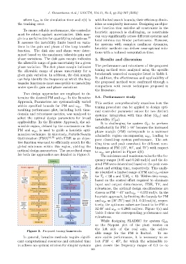
for both the approaches are detailed in Figure 3.
The minimum and maximum value for the fre-
quency ranges (0.05 and 0.249 rad/s) and the de-
sired PM were determined based on the peak over-
shoot and settling time, respectively. This analy-
sis identified a limited range of PM and ω gc values
for T s < 50 s and %M p < 10. Within this range,
based on the control effort required to eliminate
input and output disturbances, ITSE, TV, and
robustness, the optimal design specifications are
chosen as PM = 45° and ω gc = 0.153 rad/s. In the
heuristic approach, by limiting the bounds for PM
and ω gc as (30°-75°) and (0.1- 0.33 rad/s), respec-
tively, the optimum values are found to be PM =
32.48° and ω gc = 0.2965 rad/sec. Figure 4(c) and
Table 2 show the corresponding performance and
robustness.
While designing SLADRC for system G p2 ,
as the Nyquist plot of the plant resides on
the left side of the real axis, the achiev-
Figure 3. Proposed tuning frameworks
able range for the PM is limited. To en-
In general, iterative methods require signifi- sure stable performance, it is necessary to se-
◦
cant computational resources and extended time lect PM < 45 , for which the admissible re-
to achieve an optimal solution for simpler systems gion covers the frequency ranges of 0.1 to ∞
360