
Page 67 - MSAM-1-1
P. 67
Materials Science in Additive Manufacturing Thixotropic metal 3D printing
Table 1. Setup of printing parameters for the test to study the using nozzles with outlet diameters of 1 mm and 1.5 mm.
effects of nozzle size. The width of each printed line was measured, and the
results are plotted and compared, as shown in Figure 11.
Printing parameters Values
PID set value (°C) 83°C As illustrated in Figure 11, both the 1.5 mm and 1.0 mm
Extrusion speed (mm/s) 7.87 mm/s nozzles were started at a 3.81 mm/s minimum extrusion
speed. None of these nozzles, however, can print continuous
X-Y platform moving speed (mm/s) 4 mm/s straight lines at low speeds. Both nozzles can extrude
Distance between nozzle tip and substrate (mm) 15 mm thixotropic alloy on a substrate with a specified length at a
rate of 5.08 mm/s, but the printing process was not stable.
Table 2. Comparison of average (5 times) line width with When the extrusion speed was increased to 6.35 mm/s,
different nozzle diameter. the instability issue still remained, and the 1 mm nozzle
had a higher chance of producing discontinuous lines.
Nozzle diameter (mm) Average line width (mm) % Difference Stable measurements were taken at an extrusion speed
1.5 1.85 23.45% of approximately 7.62 mm/s. A nozzle with a diameter of
1.0 1.32 32.05% 1.5 mm can print a continuous line with an average width
0.8 1.01 31.21% of 1.83 mm at this extrusion speed. A 1.0 mm nozzle can
produce lines with a width of 1.34 mm at the same speed.
Increased extrusion speed resulted in more material
being squeezed out of the nozzle tip, which increased the
measured line width as well. The final speed recorded in
this test was 13.21 mm/s, and both nozzles produced lines
with a width of more than 5.5 mm. In particular, with the
1.5 mm diameter nozzle trial, the material flooded out of the
outlet at an alarming rate, making it impossible to continue
printing lines. Under the same printing conditions, both
1 mm and 1.5 mm nozzles require enough backpressure
and shear rate inside the reservoir to change the thixotropic
properties. Therefore, increasing the extrusion speed
can instantly raise the shear rate, decreasing the material
viscosity. However, when extrusion speed exceeds the stable
printing zone, the thixotropic proprieties are no longer the
primary factor to control the material flow rate.
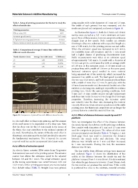
Figure 10. Comparison of printed lines with different sizes of nozzle. 4.2.3. Effect of distance between nozzle tip and X-Y
platform
is a die swell effect in thixotropic printing, and the amount Next, we investigated the effect of the distance between
of die swell seems to be dependent on the shear rate. Note the nozzle tip and the substrate on the printing resolution.
that the shear rate for the 1.5 mm nozzle is the lowest of Two nozzles with diameters of 1 mm and 1.5 mm were
the three; this may contribute to the reduced amount of used for comparison purposes. The values of other main
die swell. Nevertheless, the nature of the die swell effect in process parameters are listed in Table 4. To begin, a 1 mm
thixotropic extrusion must be studied into detail to uncover thick gage block was used to determine the distance
the fundamental mechanism. This is beyond the current between the nozzle outlet and platform. The setup
scope of work but can be incorporated into future work. distance was initially set to 1 mm and then increased
in 1 mm increments. During this test, the maximum
4.2.2. Effects of extrusion speed distance was 30 mm.
An electric linear actuator (IP66 series from Progressive The line widths from different settings were measured
Automations) was used in the printing system. The actuator and analyzed. Figure 12 shows the distribution of line
control box allows the extrusion speed to be adjusted widths as the distance between the nozzle tip and the
between 3.8 and 38.1 mm/s. The actual extrusion speed platform increased from 1 mm to 30 mm. It is demonstrated
in the testing experiments was varied between 3.81 and that when the gap distance is between 12 and 20 mm, both
13.21 mm/s. Other printing parameters are maintained at the two nozzles can produce fine metal lines. If the nozzle
their default values (Table 3). Straight lines were printed is positioned too close to the substrate, material extruded
Volume 1 Issue 1 (2022) 8 http://doi.org/10.18063/msam.v1i1.5