
Page 10 - MSAM-1-2
P. 10
Materials Science in Additive Manufacturing Flexural behavior of bio-inspired sutures
A
B
C
D
E
F
G H
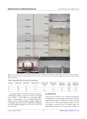
Figure 3. (A) S1 Schematic and PLA Specimen, (B) S2 Schematic and PLA Specimen, (C) S3 Schematic and PLA Specimen, (D) S3-2° Schematic and PLA
Specimen, (E) S3-5° Schematic and PLA Specimen, (F) S3-8° Schematic and PLA Specimen, (G) three-point bending test setup, (H) three-point bending
setup with specimen.
Table 1. Dimensions of the 3D printed PLA specimens
Specimen Length (mm) Width (mm) Thickness (mm) Minor radius, Major radius, Print layer Infill Number of
a (mm) b (mm) height (mm) density print layers
S1 200 44 4 1.5 2.7 0.2 100% 20
S2 200 44 4 2 3.6 0.2 100% 20
S3 200 44 4 2.5 4.5 0.2 100% 20
Eq. 1 can be utilized to calculate the total circumference, 2.2. Flexural test
C of the ellipse, while Eq. 2 and 3 can be utilized to calculate A three-point bending test was conducted according to
the arc length C´ of the ellipse at a given angle. Minor
radius – a, major radius – b, and the angle are shown in ASTM D790 to analyze the behavior of the suture structures
[50]
Figure 2A. Once the repeat length, as given in Figure 2A, under flexural loading . A 5900R Instron universal testing
is calculated, the total area can be obtained by multiplying machine with a 5 kN load cell and span length of 20 mm
the whole length by the thickness (T), which is 4 mm in all were utilized to perform the test. The length, height, and
the specimens. width of all the specimens were maintained to be 200 mm,
Volume 1 Issue 2 (2022) 4 https://doi.org/10.18063/msam.v1i2.9