
Page 9 - MSAM-1-2
P. 9
Materials Science in Additive Manufacturing Flexural behavior of bio-inspired sutures
2. Materials and methodology force. Due to the high dimensional accuracy in the printer,
two pieces were printed with the exact dimensions without
2.1. Specimen fabrication including gap tolerance. Finally, the pieces were easily fitted
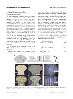
The shape of the suture is designed to be elliptical where together like a jigsaw puzzle without affecting the strength
the ratio between “a” (minor radius) and “b” (major of the final part. The S3 design was further subjected to
radius) is 1:1.8, while the angle (Ɵ) between two ellipses testing to analyze the effect of the positioning angle of
is maintained to be 25° as shown in Figure 2A. Design the suture interface since, in nature, suture structure
parameters were selected from the literature, where does not always follow a precise straight path, as shown
researchers have analyzed the dimensions of the diabolical in Figure 1A-D. Nearly straight suture lines are visible in
[24]
ironclad beetle’s suture structure . All the specimens were infant skull, but in many cases, sutures create complex
fabricated using a FDM technique with 45°/−45° print arrangement [47-49] . The schematic and PLA specimens
orientation. In comparison to 0°/90° print orientation, with slanted suture interface by 2°, 5°, and 8° are given
45°/−45° print orientation contains less porous areas in the in Figure 3D-F, respectively. Dimensions of S1, S2, and
printed structure as per the X-ray micro-CT scan images S3 specimens are given in Table 1. Dimensions of S3-2°,
in Figure 2B and D. The curved edges in the sutures are S3-5°, and S3-8° are also similar to the dimensions of S3.
perfectly covered in each layer by 45°/−45° print orientation. The areas covered by the suture interfaces in all three sizes
Still, in 0°/90° print orientation, the 90° layers could not are maintained to be ~3.65 cm , which are calculated by
2
completely cover the curved edges of the printed structure the complete elliptic integral of the second kind, multiplied
as shown in microscopic images in Figure 2C and E. PLA by the thickness of the specimen.
specimens are printed using the Prusa Mk3i printer. The
suture pattern is inspired by the interlocking connection 2 2 2 2 2
between the two elytra in the diabolical ironclad beetle (P. c 4 a cos ‚ b sin ‚d‚ (Eq. 1)
diabolicus). 0
Three different sizes of sutures were printed using t 2 2 2 2 (Eq. 2)
PLA as S1, S2, and S3; schematic diagrams are given in c‘ a cos ‚ b sin ‚d‚
Figure 3A-C. 0
Specimens were configured by connecting the two a tan b tan t (Eq. 3)
separate parts, printed together without any additional a
A
B C
D E
Figure 2. (A) Schematic of the suture design, (B) X-ray micro-CT scan of 45°/-45° print orientation, (C) microscopic images of 45°/-45° print orientation,
(D) X-ray micro-CT scan of 0°/90° print orientation, (E microscopic images of 0°/90° print orientation.
Volume 1 Issue 2 (2022) 3 https://doi.org/10.18063/msam.v1i2.9