
Page 15 - MSAM-1-2
P. 15
Materials Science in Additive Manufacturing Flexural behavior of bio-inspired sutures
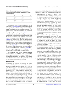
Table 2 . The percentage increments of the maximum as 2 J, 2.5 J, and 3 J. Bending stiffness values indicate that
loads in design configuration one compared to the design compared to S1, both S2 and S3 designs are harder to bend.
configuration two
(i) When changing the positioning angle of the
S1 S2 S3 suture component, the total displacement before
0° 13 % 18 % 15 % the failure was slightly increased compared to the
2° 14 % 16 % 16 % S3, in both S3-2° and S3-5°. Further increment in
5° 15 % 18 % 19 % the angle up to 8° has noticeably reduced the total
displacement at failure compared to S3 specimen
8° 14 % 21 % 19 %
as the stress is concentrated mainly in the weaker
semi suture module at the bottom rather than
Comparing the results of design configurations one and uniformly distributing through the whole suture
two, as given in Figure 9A and B, the maximum load obtained structure. In all three cases, flexural strengths and
by samples S1, S2, and S3 in configuration one is higher energy absorptions were slightly reduced compared
than in configuration two. The percentage increment of the to S3. The variation in bending stiffness values
maximum loads in design configuration one compared to suggests that by changing the positioning angle of
the design configuration two is given in Table 2. the sutures, the stiffness of the whole structure could
Similar to the experimental results, higher stress occurs be improved.
in the bottom semi suture module in every design where (ii) DIC results indicate that adjacent interlocking suture
the first failure occurs. In design configuration one, weaker modules exert tension and compression on each
bottom semi suture modules (highlighted in green circle in other due to their interlocking feature. When the top
Figure 9A) are attached to the bigger side parts, where they suture modules exert tension on the necking area of
gain support for the stress distribution; hence, this design the bottom suture module, the head of the bottom
configuration can withstand a higher load. In configuration suture module curls up and compresses the top suture
two, weaker bottom semi suture modules (highlighted in module, and instead of moving down before fracture
green circle in Figure 9B) are connected to the middle part of occurs in its necking area.
the specimen, where it gains support only from the middle (iii) Numerical simulation showed good agreement with
part for the stress distribution, as shown in Figure 9B. This the experimental results. The model was assumed to
leads the design configuration two to withstand a lower be elastic-perfectly plastic, even though FDM prints
maximum load compared to the configuration one. contain defects due to the printing process. The model
reveals that introducing larger suture modules with
This parametric study showed that the maximum less interlocking points allows more uniform stress
load the structure can withstand could be improved by distribution along the suture structure compared to
combining symmetrical suture lines, correlating with the S1 and S2, where the stress was mainly concentrated
inclined angle increment. The placement of the weaker to the suture modules at the bottom of the specimen.
link within the suture structure also significantly impacts (iv) The parametric study was performed on beam samples
the highest load the structure can withstand. with two symmetrical suture lines, which considerably
enhanced the ability to withstand a higher load. The
4. Conclusion
load-bearing ability of the structure was further
The research was conducted to investigate the flexural improved with the increment of the inclined angle. The
behavior of bio-inspired suture structures. The specimens simulation results also confirm that positioning of the
were developed with three different sizes as S1, S2, and S3 interlocking suture modules plays an important role in
using 3D printing of PLA thermoplastic while maintaining enhancing the load-bearing properties of the structure.
the ratio between the minor and major radii of the elliptical The parametric study concluded that the position of
suture shape to 1:1.8. S3 design was used to develop S3-2°, the suture components has a significant impact on the
S3-5°, and S3-8°, varying the positioning angles by 2°, 5°, mechanical performance of the whole structure.
and 8° to analyze the effect of the positioning angle. The (v) These sutures could be beneficial in many ways
S1 specimen withstood maximum load during the three- when developing a structural design. Incorporating
point bending test but failed within short displacement, a suture joint creates a pre-established crack path
whereas S3 showed higher displacement before the failure which would help to predict the fracture behavior
but with a lower maximum load. The flexural strengths of S1, by analyzing the suture pattern while maintaining
S2, and S3 were noted to be 28 MPa, 24 MPa, and 26 MPa, flexibility. As the suture joint is developed without
while the energy absorption of each design was calculated any adhesive materials, this interlocking mechanism
Volume 1 Issue 2 (2022) 9 https://doi.org/10.18063/msam.v1i2.9