
Page 109 - MSAM-3-2
P. 109
Materials Science in Additive Manufacturing NiTi lattice: Performance optimization
A C E G H
B D F
I J
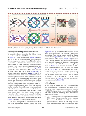
Figure 13. (A-J) Schematic diagram depicting the fatigue fracture mechanism of a Nickel titanium lattice structure.
3.5. Analysis of the fatigue fracture mechanism (Figure 13G and I), characteristic of the cleavage fracture
54
in the fracture analysis of metal materials. However, the
A schematic diagram presenting the fatigue fracture
mechanism of the two NiTi lattice structures is shown morphology of the fracture surface is different for the
in Figure 13. The red dotted lines in (Figure 13A and B) two structures (Figure 13H and J). As shown in the part
indicate the location where the sample composed of the two enclosed by red dotted lines in (Figure 13C), the stress
structures is prone to fracture when subjected to uniaxial concentration at the node is more intensive, accelerating the
compression. The BCC structure is prone to fracture at the occurrence of fatigue failure at this spot, which allows for
node, whereas the I-WP structure is prone to fracture at the observation of the relatively flat fracture morphology
the pillar. This is because the stress distribution of the BCC shown in (Figure 13H). The stress concentration at the
structure is mainly concentrated at the nodes (Figure 13C), pillar, as shown in the part circumscribed by red dotted
whereas the stress distribution of the I-WP structure lines in (Figure 13D), is more dispersed, significantly
is mainly concentrated on the pillars (Figure 13D). In slowing down the occurrence of fatigue failure at this
uniaxial compression, as shown in (Figure 13E and F), the spot, and causing the internal microstructure to break
red arrows represent tensile stresses and the blue arrows after undergoing longer cyclic loading. These deductions
denote compressive stresses. Under compressive loads, the are reflected in the fracture observed in the NiTi lattice
area marked by red arrows produces tensile stress under structures shown in Figure 8. Obvious cleavage steps
tension, and the area marked by blue arrows produces formed are shown in (Figure 13J).
compressive stress under compression. When the BCC
structure is subjected to cyclic compression, there is a 4. Conclusion
greater stress concentration at the joint. After a certain In this study, NiTi BCC and I-WP lattice structures
number of cycles, the joint becomes more susceptible to were prepared by the LPBF process. The microstructure,
fatigue fracture. In contrast, when the I-WP structure is mechanical properties, and fatigue properties of BCC and
subjected to cyclic compression, there is a greater stress I-WP NiTi lattice structures were studied experimentally.
concentration at the pillar. After a certain number of The main conclusions stemming from this work are
cycles, the pillar becomes more vulnerable to fatigue summarized as follows:
fracture. This proposed mechanism offers some insights (i) The NiTi lattice structure samples prepared by the
into how the fractures resulted in the samples, as shown in LPBF process share almost similar forming accuracy.
Figures 3 and 8, due to compression and fatigue. The surfaces of both BCC and I-WP lattice structures
It is worth noting that the fracture surfaces of the produced by LPBF process are very rough, attached
two metal structures are relatively smooth and bright with numerous powder particles, especially at the
Volume 3 Issue 2 (2024) 12 doi: 10.36922/msam.3380