
Page 108 - MSAM-3-2
P. 108
Materials Science in Additive Manufacturing NiTi lattice: Performance optimization
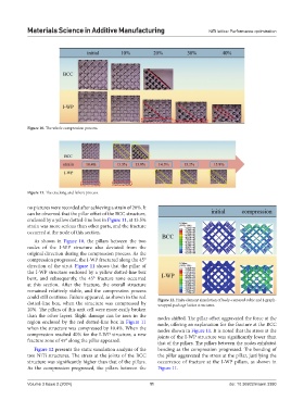
Figure 10. The whole compression process.
Figure 11. The cracking and failure process.
no pictures were recorded after achieving a strain of 20%. It
can be observed that the pillar offset of the BCC structure,
enclosed by a yellow dotted-line box in Figure 11, at 13.5%
strain was more serious than other parts, and the fracture
occurred at the node of this section.
As shown in Figure 10, the pillars between the two
nodes of the I-WP structure also deviated from the
original direction during the compression process. As the
compression progressed, the I-WP fractured along the 45°
direction of the strut. Figure 11 shows that the pillar of
the I-WP structure enclosed by a yellow dotted-line box
bent, and subsequently, the 45° fracture zone occurred
at this section. After the fracture, the overall structure
remained relatively stable, and the compression process
could still continue. Failure appeared, as shown in the red Figure 12. Finite element simulation of body-centered cubic and I-graph-
dotted-line box, when the structure was compressed by wrapped package lattice structures.
20%. The pillars of this unit cell were more easily broken
than the other layers. Slight damage can be seen in the nodes shifted. The pillar offset aggravated the force at the
region enclosed by the red dotted-line box in Figure 11 node, offering an explanation for the fracture at the BCC
when the structure was compressed by 10.4%. When the nodes shown in Figure 11. It is noted that the stress at the
compression reached 40% for the I-WP structure, a new joints of the I-WP structure was significantly lower than
fracture zone of 45° along the pillar appeared. that of the pillars. The pillars between the nodes exhibited
Figure 12 presents the static simulation analysis of the bending as the compression progressed. The bending of
two NiTi structures. The stress at the joints of the BCC the pillar aggravated the stress at the pillar, justifying the
structure was significantly higher than that of the pillars. occurrence of fracture at the I-WP pillars, as shown in
As the compression progressed, the pillars between the Figure 11.
Volume 3 Issue 2 (2024) 11 doi: 10.36922/msam.3380