
Page 81 - MSAM-4-3
P. 81
Materials Science in Additive Manufacturing Interpretable GP melt track prediction
The statistical results are presented in Figure 7. in the area and width of the actual melt pool needs to be
From Figure 8, it can be seen that the regular further verified.
morphology has stable geometric features, corresponding 2.4. Melt track theory model
to a small change in the geometric features of the melt 31-34
pool. For melt track defects involving width distortion, Existing studies on 316L, Ti-6Al-4V, and Inconel718
such as necking and protrusion, the melt pool morphology materials have consistently demonstrated that powder bed
exhibits distinct changes. During necking, the melt pool coverage has no significant effect on melt pool width. Guo
16
area and aspect ratio decrease significantly. Conversely, et al. also verified that, in the case of ignoring the random
during protrusion, the melt pool area, aspect ratio, and spattering and flaking of powder, it can be assumed that
convexity increase significantly. Therefore, the melt track the powder consumption width and the melt track width
width may be determined by a combination of the melt are approximately equal. Therefore, this study assumes that
pool area, aspect ratio, and convex defects. the powder consumption width is equal to the theoretical
track width.
For defects in which the melt track deviates from the
preset scanning path (i.e., distorted morphology), the area Assuming that the upper profile curve of the melt track
of the melt pool and the y-axis coordinates of the center of above the substrate surface is bow-shaped (Figure 9A), for
mass change significantly, and the extent of the deviation points on the curve (x ,y ) to meet the center of the circle
0
0
35,36
of the melt track may be jointly determined by the area of (0,y R), the radius R can be expressed as Equation V.
the melt pool and the y-axis coordinates of the center of x +( y − y ) 2 = R 2 (V)
2
mass. o o R
Based on the conservation of mass, Equation VI is
For defects with distortion in the height of the melt track derived. Similarly, based on the bowing geometry, a
(i.e., hump shape), the area of the melt pool decreases and relationship can be derived between the width W, radius
the aspect ratio increases. The upward shift of the center of R, height H, and the bowing area (Equations VII and VIII).
mass of the melt pool indicates an increase in the height of
the melt track, which may be due to the limitation of the ρ powder LWL track = ρLA track (VI)
viewing angle of the monitoring equipment. The change 2
W = 22 RHH− (VII)
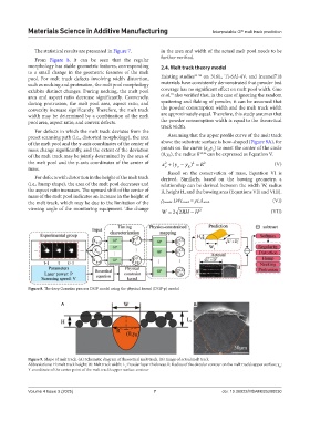
Figure 8. The deep Gaussian process DGP model using the physical kernel (DGP-p) model
A B
Figure 9. Shape of melt track. (A) Schematic diagram of theoretical melt track. (B) Image of actual melt track
Abbreviations: H: melt track height; W: Melt track width; L : Powder layer thickness; R: Radius of the circular contour on the melt track’s upper surface; y :
R
t
Y-coordinate of the center point of the melt track’s upper surface contour
Volume 4 Issue 3 (2025) 7 doi: 10.36922/MSAM025200030