
Page 473 - IJB-10-2
P. 473
International Journal of Bioprinting Bioprinting with ASCs and bioactive glass
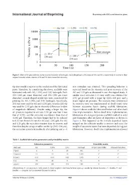
Figure 5. Effect of B3 glass addition on the recovery behavior of hydrogels. AG hydrogel and 1.25G required 90 s and 60 s, respectively, to recover to their
original viscosity values, whereas 2.5G and 5G show immediate recovery.
tip sizes would compromise the resolution of the fabricated mm extrudate was obtained. This spreading behavior is
parts. Therefore, by considering the above, scaffolds were expected based on the viscosity and poor recovery of the
fabricated only with AG, 1.25G, and 2.5G hydrogels. Both AG and 1.25 gels as discussed in our rheological study. A
22G (410 µm inner diameter) and 25G (250 µm inner similar sized extrudate (~1 mm) width was obtained for
diameter) conical-shaped nozzle tips were considered for 2.5G gel printed with a larger tip (22G–410 µm) and a
printing the AG, 1.25G, and 2.5G hydrogels. Specifically, much higher air pressure. The recovery time determined
25G tips were used for AG and 1.25G gels, whereas 22G tip by recovery tests was implemented as dwell (wait) time
was used for 2.5G gels due to viscosity differences (orders between successive layers during scaffold fabrication.
of magnitude different). Despite using a larger tip, the Figure 6 shows scaffolds fabricated before and after dwell
air pressure required to extrude 2.5G gel was four times time implementation. Before dwell time implementation,
that of 1.25G, and the extrudate was thinner than that of fabrication of a designed porous scaffold resulted in solid
1.25G gel. Therefore, the layer height had to be reduced part formation after six layers of deposition as shown in
to 0.12 mm from 0.14 mm for AG and 1.25G gels. For AG Figure 6. This happened as the initially deposited layers
and 1.25 gels, the extrudate requires time to recover, and merged on the substrate unable to recover and carry the
therefore despite using a smaller nozzle tip (25G–250 µm), weight of successive layers that were deposited during part
the extrudate spreads immediately after printing and a ~1 fabrication. However, dwell time implementation allowed
Table 1. Scaffold fabrication parameters and printability matrix
Fabrication parameters Printability matrix
Hydrogel AG 1.25G 2.5G Hydrogel 3D part printability Filament formation
P (psi) 4 5 20 AG
S (mm/s) 15 15 15 1.25G
h (mm) 0.14 0.14 0.12 2.5G
t (s) 90 60 0 5G ~
φ (µm) 250 250 410 10G ~
Abbreviations: P—air pressure; S—table speed; h—layer height; t—wait time between layers; φ—nozzle tip internal diameter; —feasible; —not
feasible; ~—irregular and inconsistent filament formation.
Volume 10 Issue 2 (2024) 465 doi. 10.36922/ijb.2057