
Page 467 - IJB-9-4
P. 467
International Journal of Bioprinting β-Ti21S auxetic FGPs produced by laser powder bed fusion
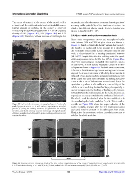
The excess of material at the corner of the auxetic cell is excess of material at the corners increases, denoting reduced
evident in all the relative density levels without differences. accuracy in the printability of the strut-base structure. No
Higher amount of material in the corner is observed effect of the different relative density levels is detected also
considering the auxetic structure with θ = 25° at a relative in case of auxetic with θ = 25°.
density of 0.40 (Figure 14D), 0.58 (Figure 14E) and 0.75
(Figure 14F). Therefore, with an increase of the θ angle, the 3.4. Quasi-static and cyclic compression tests
Quasi static compression curves and examples of cyclic
A B tests between 20% and 70% of yield stress are shown in
Figure 15. Based on Maxwell’s stability criteria that consider
the number of nodes and struts present in a structure,
the re-entrant honeycombs auxetic structure used in this
work is characterized by a bending-dominated behavior
(M < 0) . Despite this, after the yielding point, the quasi-
[22]
static compression curves for the two FPGSs (Figure 15A)
C D show two small collapses (indicated with number 1 and 2
on the curves) in both auxetic structures. Details of the two
collapses are shown in Figure 15C for both auxetic structures.
After that, a densification stage occurs, leading to an increased
slope of the stress-strain curve until a fully dense material is
obtained. Quasi-elastic modulus as the slope of the linear part
of the curve and yield stress obtained by shifting the linear
E F curve at the 0.2% of deformation are evaluated. Since the
quasi-elastic gradient is affected by the poor stability of the
cellular structures during the first loading cycle, especially in
case of high porosity, five loading-unloading cycles between
20% and 70% of the yield stress (i.e., in the elastic deformation
regime) are necessary to stabilize the mechanical behavior .
[41]
The elastic modulus obtained after the first stabilization is
the so-called cyclic elastic modulus, E cyclic. This is evident
Figure 13. Light optical microscopy micrographs of auxetic functionally considering Figure 15B, where the slope, indicative of the
graded porous structures (A, B) with surface irregularity and unmelted elastic modulus, changes after the first loading-unloading
powder, (C) along the building direction, (D) parallel to the building cycle and remains constant in the subsequent four cycles.
direction, and (E, F) scanning electron microscopy micrograph details
at higher magnification to highlight b grains, melting pool interface and This justifies the necessity to preload the cellular structure to
unmelted powders. stabilize the elastic modulus.
A B C
D E F
Figure 14. Scanning electron microscopy details of the strut surface irregularities and of the excess of material at the corners of auxetic structure with
θ = 15° and relative density of (A) 0.34, (B) 0.49, (C) 0.66, and with θ = 25° and relative density of (D) 0.40, (E) 0.58, and (F) 0.75.
Volume 9 Issue 4 (2023) 459 https://doi.org/10.18063/ijb.728