
Page 12 - IJOCTA-15-4
P. 12
M. A. Aman et al. / IJOCTA, Vol.15, No.4, pp.549-577 (2025)
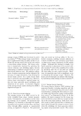
Table 1. Classification and characteristics of switched reluctance motor modeling techniques
Classification Methodology Advantage Disadvantage
Exhibiting high precision,
this approach is proficient
in managing complex Prolonged computational
Finite element
Numerical methods analysis configurations, effectively time and complex modeling
capturing field distributions while procedure for 3D geometry.
accommodating 3D effects,
such as skewing and winding impacts.
System matrix with a high
population density, limited
Outstanding accuracy and
Boundary element acceptable computational capacity to address saturation
method or nonlinear issues,
efficiency.
and requires the resolution
of boundary conditions.
Increased complexity,
constrained ability to
Fast computational speed, tackle saturation or nonlinear
Maxwell’s equations-based obtains magnetic properties challenges, the need for empirical
approach directly, effective computation, and heuristic approaches necessitate
Analytical methods
(curve fitting method) and infers patterns from pre-established data, and the
a small set of data. introduction of new data
is essential in the event
of a topology alteration.
Depend on empirical
conventions related to
Magnetic equivalent Minimal computation time fringing and leakage reluctances,
circuit and satisfactory accuracy. necessitating a predefined
description of flux
paths prior to analysis.
Source: Details are available in the previous review by Diao et al. 19
average torque of SRMs was introduced in previ- data are stored as look-up tables in the con-
ous studies. 21,22 The average torque control strat- troller’s memory, enabling accurate selection of
egy is implemented using an online method to es- control variables for each operating mode based
timate the average torque and energy ratio within on shaft speed, torque command, and DC supply
a closed-loop control system. The torque refer- voltage. Although this strategy is simple, it is
ence is dynamically regulated by adjusting the highly sensitive to alterations in the motor’s defi-
current reference and switching angles, thereby nite variables 16 and is often considered too costly
maintaining a consistent average torque at a pre- for industrial uses due to the need for storing
determined reference level. The adaptive adjust- 3D data tables for each control variable. More-
ment of system parameters further enhances the over, its simplicity may lead to significant errors
accuracy of torque estimation, thus allowing for in estimating the average torque. However, AI-
precise torque control. As a result, torque ripple based control strategies can enhance this strategy
can be reduced to an acceptable level. However, by facilitating online tuning of control variables. 23
during phase commutation, residual torque rip-
ples can cause noticeable speed oscillations and
variations at low speeds. A schematic diagram 3.1.1.3. Torque sharing function
of the average torque control strategy for SRM is The torque sharing function (TSF) strategy has
depicted in Figure 8.
numerous benefits, including simplicity and effi-
ciency. It is implemented using the motor’s static
characteristics, enabling the drive system to oper-
3.1.1.2. Open-loop current sharing ate under either hysteresis or pulse-width modula-
The average torque of an SRM cannot be di- tion control, 23 as illustrated in Figure 10. In this
rectly identified from phase current measure- method, the input command for the torque sig-
ments. Consequently, an open-loop current shar- nal is divided into phase reference torques accord-
ing strategy can be applied. To implement this ing to the rotor angle position. Each phase refer-
technique, it is essential to determine the switch- ence torque is then converted into a current com-
ing angles and command currents (θ OFF and θ ON ) mand signal through the torque-to-current block,
either through offline analysis or experimental while the switching rule block generates switch-
testing, as depicted in Figure 9. The generated ing signals using hysteresis control. The current
554